
Chapter 5: Drawing & Typing
Contents
5.1 Drawing: Overview
AspJpeg.NET is equipped with a versatile set of drawing routines which enable your application to draw high-quality antialiased graphics and text on top of an image. All the drawing methods are incapsulated by the JpegCanvas object which is accessible via the JpegImage.Canvas property. For example, the following code draws a line:
The drawing operations are all subject to the current drawing parameters such as the stroking color, line width, fill color, opacity, etc. These parameters are specified via the properties of the JpegPen and JpegBrush objects accessible via JpegCanvas's Pen and Brush properties, respectively. The JpegPen object is responsible for stroking operations, and JpegBrush for filling operations. For example, the following code sets the line width to 5:
This section of the chapter will focus on drawing graphics. Drawing text is described in detail in the Section 5.3 of this chapter.
5.1.2 Path-based Drawing Model
The central notion in AspJpeg.NET's drawing model is a path, which is a composition of straight and curved line segments which may connect to one another or may be disconnected.
A straight line is defined by two points - the current point and endpoint. A curved path segment is specified as a Cubic Bezier Curve. Such curves are defined by four points: the two endpoints (the current point P0 and the final point P3) and two control points P1 and P2. The curve does not, in general, pass through the control points:
A path is made up of one or more disconnected subpaths, each comprising a sequence of connected segments. Typically, a subpath is defined by specifying its starting point, appending one or more segments to it, and then closing it. Once a path is defined, it is painted by stroking, filling, or both.
With AspJpeg.NET, a new path, or a new subpath within an existing path, is created by calling the JpegCanvas.MoveTo method. This establishes the first current point of the path (or subpath). A straight line is added to the path via JpegCanvas.LineTo, and a curve via JpegCanvas.CurveTo. The current path or subpath is closed by calling JpegCanvas.ClosePath. Once the entire path is built, it is stroked with JpegCanvas.Stroke, filled with JpegCanvas.Fill, or both filled and stroked with JpegCanvas.FillStroke.
The following code snippet draws a 5-end star on a new blank image with a while background (0xFFFFFFFF). The pen color is blue (0xFF0000FF) and brush color is gray (0xFF808080). The pen width is 6.
JpegImage objImage = objJpeg.CreateImage(300, 300, 0xFFFFFFFF);
objImage.Canvas.Pen.Width = 6;
objImage.Canvas.Brush.Color = 0xFF808080;
objImage.Canvas.Pen.Color = 0xFF0000FF;
objImage.Canvas.MoveTo(150, 50);
objImage.Canvas.LineTo(209, 231);
objImage.Canvas.LineTo(55, 119);
objImage.Canvas.LineTo(245, 119);
objImage.Canvas.LineTo(91, 231);
objImage.Canvas.ClosePath();
objImage.Canvas.FillStroke();
objImage.Save( @"c:\path\output.jpg" );
The following code snippet draws a propeller-like figure by defining and filling a path made up of two subpaths:

objImage.Canvas.MoveTo(306, 96);
objImage.Canvas.CurveTo(446, 196, 166, 396, 306, 496);
objImage.Canvas.ClosePath();
objImage.Canvas.MoveTo(106, 296);
objImage.Canvas.CurveTo(206, 156, 406, 436, 506, 296);
objImage.Canvas.ClosePath();
objImage.Canvas.Fill();
5.1.3 Filling Rules
The Fill and FillStroke methods used in the previous section paint the insides of all the subpaths of a current path, considered together. Any subpaths that are open are implicitly closed before being filled. For a simple path, it is intuitively clear what region lies inside. However, for a more complex path -- for example, a path that intersects itself or has one subpath that encloses another -- the interpretation of "inside" is not always obvious. The path machinery uses one of two rules for determining which points lie inside a path: the nonzero winding number rule and the even-odd rule.
The nonzero winding number rule determines whether a given point is inside a path by conceptually drawing a ray from that point to infinity in any direction and then examining the places where a segment of the path crosses the ray. Starting with a count of 0, the rule adds 1 each time a path segment crosses the ray from left to right and subtracts 1 each time a segment crosses from right to left. After counting all the crossings, if the result is 0 then the point is outside the path; otherwise it is inside.
An alternative to the nonzero winding number rule is the even-odd rule. This rule determines the "insideness" of a point by drawing a ray from that point in any direction and simply counting the number of path segments that cross the ray, regardless of direction. If this number is odd, the point is inside; if even, the point is outside. This yields the same results as the nonzero winding number rule for paths with simple shapes, but produces different results for more complex shapes.
By default, AspJpeg.NET uses the nonzero winding number rule. To use the even-odd rule, the Fill and FillStroke methods should be called with true passed to them, as follows:
The 5-end start drawing code above would produce the following result if true were passed to the FillStroke method:
5.1.4 Stroke Parameters: Width, Cap and Join Styles
The current line width is set via the Canvas.Pen.Width property which is set to 1 by default. A line width can be a fractional number.
The Canvas.Pen.CapStyle property specifies the shape to be used at the ends of open subpaths (and dashes, if any) when they are stoked. The CapStyle property can be set to one of three values:
0: Butt cap. The stroke is squared off at the endpoint of the path. There is no projection beyond the end of the path. This is the default value.
1: Round cap. A semicircular arc with a diameter equal to the line width is drawn around the endpoint and filled in.
2: Projecting square cap. The stroke continues beyond the endpoint of the path for a distance equal to half the line width and is then squared off.
The Canvas.Pen.JoinStyle property specifies the shape to be used at the corners of paths that are stroked. The JoinStyle property can be set to one of three values:
0: Miter join. The outer edges of the strokes for the two segments are extended until they meet at an angle. If the segments meet at too sharp an angle (as defined by the miter limit parameter described below), a bevel join is used instead. This is the default style.
1: Round join. A circle with a diameter equal to the line width is drawn around the point where the two segments meet and is filled in, producing a rounded corner.
2: Bevel join. The two segments are finished with butt caps and the resulting notch beyond the ends of the segments is filled with a triangle.
When two line segments meet at a sharp angle and mitered joins have been specified as the line join style, it is possible for the miter to extend far beyond the thickness of the line stroking the path. The miter limit imposes a maximum on the ratio of the miter length to the line width. When the limit is exceeded, the join is converted from a miter to a bevel. The miter limit can be specified via the Canvas.Pen.MiterLimit property, which is 10 by default.
5.1.5 Line Dash Pattern
The line dash pattern controls the pattern of dashes and gaps used to stroke paths. It is specified by a dash array and a dash phase. The dash array’s elements are numbers that specify the lengths of alternating dashes and gaps; the dash phase specifies the distance into the dash pattern at which to start the dash. By default, the dash value array is empty (null) and dash phase is 0, which corresponds to a solid, unbroken line.
The dash patten array is specified via the Canvas.Pen.DashPattern property which expects an array of float's. By default, this property is null which corresponds to a solid line. The dash phase is specified via the Canvas.Pen.DashPhase property, which is 0 by default.
The following five code snippets produce patterns displayed below:
objImage.Canvas.Pen.DashPatten = new float[1] { 3 };
objImage.Canvas.Pen.DashPhase = 0;
// 2
objImage.Canvas.Pen.DashPatten = new float[1] { 2 };
objImage.Canvas.Pen.DashPhase = 1;
// 3
objImage.Canvas.Pen.DashPatten = new float[2] { 2, 1 };
objImage.Canvas.Pen.DashPhase = 0;
// 4
objImage.Canvas.Pen.DashPatten = new float[2] { 3, 5 };
objImage.Canvas.Pen.DashPhase = 6;
// 5
objImage.Canvas.Pen.DashPatten = new float[2] { 2, 3 };
objImage.Canvas.Pen.DashPhase = 11;
5.2 Shortcut Drawing Routines
The low-level Path-building routines described in the previous section, such as MoveTo, LineTo and CurveTo, can be used to draw a shape of any complexity. However, using these to draw something as simple as a circle is not a trivial task, and involves math. To simplify the drawing of basic shapes such as lines, rectangles, circles, ellipses and arcs, the JpegCanvas object provides several "shortcut" methods that do the job in a single line of code.
These shortcut routines are:
DrawEllipse
DrawLine
DrawRect
DrawRoundRect
DrawSegment
FillArc
FillEllipse
FillRect
FillRoundRect
FillSegment
The DrawXXX routines are subject to the current Canvas.Pen properties: CapStyle, Color, DashPattern, DashPhase, JoinStyle, MiterLimit, Opacity, and Width. The FillXXX routines are subject to the current Canvas.Brush properties: Color, Opacity and Solid.
Let's review these routines in the order of complexity.
The following code draws a line from point (10, 20) to point (150, 300):
The following code draws the outline of an ellipse with the center in (500, 400), horizontal radius of 150 and vertical radius of 100. To draw a filled ellipse, FillEllipse with the same arguments should be called instead.
If the radii are equal, the ellipse becomes a circle.
The following code draws the outline of a rectangle with the upper-left corner in (50, 30), width of 500 and height of 400. To draw a filled rectangle, FillRect with the same arguments should be called instead.
The following code draws the outline of a rectangle with rounded corners with the upper-left corner in (10, 10), width of 120, height of 100, horizontal corner radius of 20 and vertical corner radius of 30. To draw a filled rectangle with rounded corners, FillRoundRect with the same arguments should be called instead.

The following code draws the arc of an ellipse with the center in (250, 250), horizontal radius of 200 and vertical radius of 100. The arc begins at -10° (λ1) relative to the X-axis of the ellipse (shown in blue) and ends at 90° (λ2). The ellipse itself is tilted 20° (Θ) relative to the X-axis. See the diagram below.
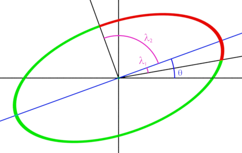
To draw a filled arc, FillArc with the same arguments should be called instead. To draw and fill the segment of an ellipse, the methods DrawSegment and FillSegment should be used. The arguments for these methods have the same meaning as those for DrawArc described above.
5.3 Text Drawing with PrintText
AspJpeg.NET supports the drawing of high-quality anti-aliased text over the image using an arbitrary TrueType/OpenType font with the JpegCanvas.PrintText method.
PrintText offers the following features:
- The font to be used is specified via a physical path or a byte array. Therefore, the font does not have to be properly registered on the machine as long as the font file or its binary data is available. Both TrueType/OpenType and Type 1 fonts are supported.
- Automatic word wrapping. CR/LF characters can be used in the text string for hard line breaks.
- Text alignment to the left, right, center, and justified.
- Adjustable opacity for image watermarking.
- Text can be rotated around the origin.
- For multi-line text, line spacing can be adjusted.
- The method returns the width of the string being drawn, and the height of the text paragraph (the latter via a separare property Canvas.ParagraphHeight.)
PrintText expects 4 parameters: the text string to draw, the x and y coordinates, and the physical path to a TrueType/OpenType or Type 1 font to draw it with (or an array of bytes containing the font file). The coordinates specify the position of the lower-left corner of the first character of the first line of text to be drawn, in the image coordinate system.
In addition to these arguments, the text rendering process is also subject to the properties of the JpegFont object accessible via the JpegCanvas.Font property. The JpegFont properties are: Align, Color, Opacity, Rotation, Size, Spacing, Underlined, and Width.
The following code snippet uses the system font Arial to draw the text string "ABC" in size 20 and red color:
objImage.Canvas.Font.Color = 0xFFFF0000; //Red
objImage.Canvas.PrintText( "ABC", 10, 50, @"c:\Windows\Fonts\Arial.ttf" );
If the location of the Windows directory is not known in advance, the property JpegManager.WindowsDirectory should be used, so the last line may be rewritten as follows:
objImage.Canvas.PrintText( "ABC", 10, 50,
objJpeg.WindowsDirectory + @"\Fonts\Arial.ttf" );
As mentioned above, PrintText supports automatic word wrapping. This functionality is enabled by setting the property Font.Width to a non-zero value (in pixels). The text to be drawn can also contain CR/LF characters for hard line breaks.
If Font.Width is specified, text alignment can also be specified via Font.Align. The supported values are 0 (left, default), 1 (right), 2 (center) and 3 (justified). You can also adjust the distance (in pixels) between the lines via Font.Spacing. A positive value increases the default line spacing, a negative one decreases it.
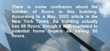
The justified text on the image below was produced by the following code snippet:
objImage.Canvas.Font.Color = 0xFFFFFFFF; // white
objImage.Canvas.Font.Align = 3; // justify
objImage.Canvas.Font.Width = 300;
objImage.Canvas.Font.Size = 15;
objImage.Canvas.Font.Spacing = 2;
objImage.Canvas.PrintText( Text, 210, 160, @"c:\Windows\Fonts\Arial.ttf" );
For image watermarking purposes, text opacity can be modified by setting the Font.Opacity property to a value between 0 (fully transparent) and 1 (fully opaque). The image below was created via the following code:
objImage.Canvas.Font.Size = 18;
objImage.Canvas.Font.Opacity = 0.5;
objImage.Canvas.PrintText( Text, 160, 230, @"c:\Windows\Fonts\Arial.ttf" );

Text rotation is activated by setting the Font.Rotation property (in degrees). Text is rotated around the point specified by the x and y coordinates described above. A positive Rotation value produces a counter-clockwise rotation.
PrintText also supports text underlining. To enable this feature, set the property Font.Underlined to true. The width and color of the line used for the underlining are specified via the properties Pen.Width and Pen.Color, respectively.
PrintText returns the width of the text string being drawn (in pixels) or, in case of multi-line text, the width of the longest line in the paragraph. The height of the text paragraph rendered by the most recent call to PrintText can be obtained from the read-only property Canvas.ParagraphHeight.
The following code sample displays a text string in a round-about manner.
<%@ Import Namespace="Persits.Jpeg"%>
<html>
<head>
<title>AspJpeg.NET User Manual Chapter 5 - Text Drawing</title>
<script runat="server" languge="C#">
void Page_Load( Object Source, EventArgs E)
{
// Create instance of JpegManager
JpegManager objJpeg = new JpegManager();
string strPath = Server.MapPath("../images/apple.jpg");
string strFontPath = objJpeg.WindowsDirectory + @"\fonts\courbd.ttf";
JpegImage objImage = objJpeg.OpenImage(strPath);
string strText = "* APPLES ARE A GREAT SOURCE OF VITAMINS ";
objImage.Canvas.Font.Color = 0xFFFF00; // Yellow
objImage.Canvas.Font.Size = 60;
float fAngle = -275;
for( int i = 0; i < strText.Length; i++)
{
int x = (int)(280 * Math.Cos( fAngle * Math.PI / 180.0 ) +
objImage.Width / 2);
int y = (int)(280 * Math.Sin( fAngle * Math.PI / 180.0 ) +
objImage.Height / 2);
objImage.Canvas.Font.Rotation = 270.0f - fAngle;
float w = objImage.Canvas.PrintText( strText.Substring(i, 1),
x, y, strFontPath );
fAngle = fAngle + 360.0f / strText.Length;
}
string strFilename = objImage.SaveUnique(
Server.MapPath("apple_small.jpg"));
OutputImage.ImageUrl = strFilename;
}
</script>
</head>
<form runat="server">
<asp:image runat="server" id="OutputImage"/>
</form>
</html>
<%@ Import Namespace="Persits.Jpeg"%>
<html>
<head>
<title>AspJpeg.NET User Manual Chapter 5 - Text Drawing</title>
<script runat="server" languge="vb">
Sub Page_Load(Source As Object, E As EventArgs)
'Create instance of JpegManager
Dim objJpeg As JpegManager = New JpegManager()
Dim strPath As String = Server.MapPath("../images/apple.jpg")
Dim strFontPath As String = objJpeg.WindowsDirectory +
"\fonts\courbd.ttf"
Dim objImage As JpegImage = objJpeg.OpenImage(strPath)
Dim strText As String = "* APPLES ARE A GREAT SOURCE OF VITAMINS "
objImage.Canvas.Font.Color = &HFFFF00 ' Yellow
objImage.Canvas.Font.Size = 60
Dim fAngle As Single = -275
Dim x As Integer, y As Integer
Dim w As Single
For i As Integer = 0 To strText.Length - 1
x = (280 * Math.Cos(fAngle * Math.PI / 180.0) +
objImage.Width / 2)
y = (280 * Math.Sin(fAngle * Math.PI / 180.0) +
objImage.Height / 2)
objImage.Canvas.Font.Rotation = 270.0F - fAngle
w = objImage.Canvas.PrintText(strText.Substring(i, 1),
x, y, strFontPath)
fAngle = fAngle + 360.0 / strText.Length
Next
Dim strFilename As String = objImage.SaveUnique(
Server.MapPath("apple_small.jpg"))
OutputImage.ImageUrl = strFilename
End Sub
</script>
</head>
<form runat="server">
<asp:image runat="server" id="OutputImage"/>
/form>
</html>
Click the links below to run this code sample:


