
Chapter 11: 3D Surface Mapping
Contents
11.1 Introduction to 3D Surface Mapping & Quick Start
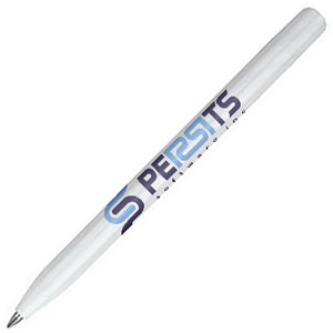
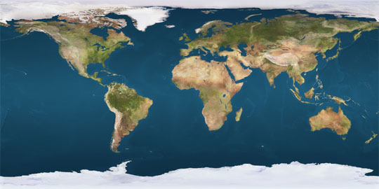
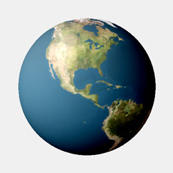
As of Version 2.8, AspJpeg.NET is capable of displaying an image mapped to an arbitrary 3D surface such as a sphere, cylinder, cone (or a portion thereof) or any other mathematically defined surface. This feature is useful for creating the images of promotional items such as coffee mugs, baseball caps, pens, etc. with custom logos or photographs wrapped around them in a realistic way.
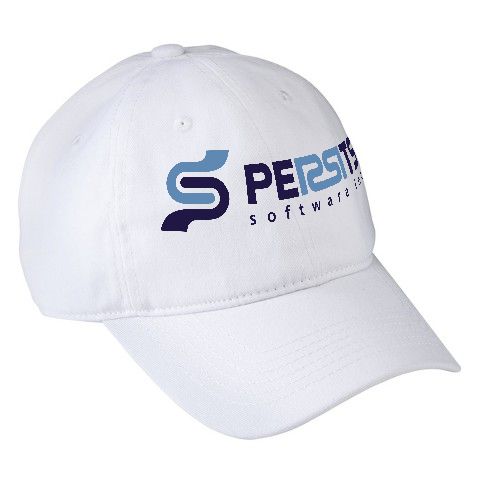
[Pic. 1: Logo on a Baseball Cap]

[Pic. 2a: Logo on a Pen with Shading]
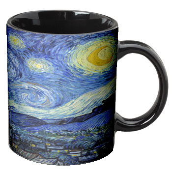
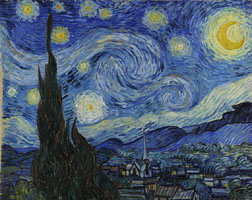
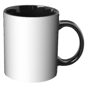
[Pic. 2b: Image of a Painting on a Coffee Mug with Shading]
The new functionality is implemented via a new Canvas method, DrawImageUV, which accepts a single argument: another instance of the JpegImage \ object containing the image to be mapped to a 3D surface. The surface equations as well as numerous other parameters controlling the mapping process are specified via the properties and methods of the new JpegUV object accessible via the Canvas.UV property. The letter combination "UV" refers to the traditional names (U, V) of the parameters in the three parametric equations defining an arbitrary 3D surface. The UV object is described below in great detail.
The above picture of a logo wrapping around the spherical shape of a baseball cap (Pic. 1) is created via the following code snippet (the Pic. 2a script is provided in Section 11.5 - Shading and Pic. 2b script in Section 11.6 - Putting It All Together):
<%@ Import Namespace="Persits.Jpeg"%>
<html>
<head>
<title>AspJpeg.NET User Manual Chapter 11 -- Logo on Baseball Cap</title>
<script runat="server" languge="C#">
void Page_Load( Object Source, EventArgs E)
{
// Create instance of JpegManager
JpegManager objJpeg = new JpegManager();
// Open image of a baseball cap as background
JpegImage objBkImage =
objJpeg.OpenImage(Server.MapPath("../images/cap.jpg"));
// Open logo image to map to 3D surface
JpegImage objImage =
objJpeg.OpenImage(Server.MapPath("../images/ps_logo.png"));
// Specify UV parameters
JpegUV objUV = objBkImage.Canvas.UV;
// Parametric equations of a spheroid
objUV.XFunc = "cos(v) * cos(u)";
objUV.YFunc = "cos(v) * sin(u)";
objUV.ZFunc = "1.25 * sin(v)";
objUV.UMin = - Math.PI / 4;
objUV.UMax = Math.PI / 4;
objUV.VMin = 0.4f;
objUV.VMax = 0.8f;
objUV.UStep = 20;
objUV.VStep = 10;
// Fine-tuning the position over canvas
objUV.ShiftX = -19;
objUV.ShiftY = -3;
// Camera view angle
objUV.CameraAngle = 34;
// Do now show portion of the surface over the cap's "horizon"
objUV.HideBackFace = true;
// Camera location and rotation
objUV.CameraX = 2.4f;
objUV.CameraY = 0.1f;
objUV.RotateCameraAroundAxes( 0, -30, -30 );
// Draw image on the canvas
objBkImage.Canvas.DrawImageUV( objImage );
string strFilename =
objBkImage.SaveUnique(Server.MapPath("caplogo.jpg"));
OutputImage.ImageUrl = strFilename;
}
</script>
</head>
<form runat="server">
<asp:image runat="server" id="OutputImage"/>
</form>
<%@ Import Namespace="Persits.Jpeg"%>
<html>
<head>
<title>AspJpeg.NET User Manual Chapter 11 -- Logo on Baseball Cap</title>
<script runat="server" languge="vb">
Sub Page_Load( Source As Object, E As EventArgs)
' Create instance of JpegManager
Dim objJpeg As JpegManager = New JpegManager()
' Open image of a baseball cap as background
Dim objBkImage As JpegImage =
objJpeg.OpenImage(Server.MapPath("../images/cap.jpg"))
' Open logo image to map to 3D surface
Dim objImage As JpegImage =
objJpeg.OpenImage(Server.MapPath("../images/ps_logo.png"))
' Specify UV parameters
Dim objUV As JpegUV = objBkImage.Canvas.UV
' Parametric equations of a spheroid
objUV.XFunc = "cos(v) * cos(u)"
objUV.YFunc = "cos(v) * sin(u)"
objUV.ZFunc = "1.25 * sin(v)"
objUV.UMin = -Math.PI / 4
objUV.UMax = Math.PI / 4
objUV.VMin = 0.4F
objUV.VMax = 0.8F
objUV.UStep = 20
objUV.VStep = 10
' Fine-tuning the position over canvas
objUV.ShiftX = -19
objUV.ShiftY = -3
' Camera view angle
objUV.CameraAngle = 34
' Do now show portion of the surface over the cap's "horizon"
objUV.HideBackFace = True
' Camera location And rotation
objUV.CameraX = 2.4F
objUV.CameraY = 0.1F
objUV.RotateCameraAroundAxes(0, -30, -30)
' Draw image on the canvas
objBkImage.Canvas.DrawImageUV(objImage)
Dim strFilename As String =
objBkImage.SaveUnique(Server.MapPath("caplogo.jpg"))
OutputImage.ImageUrl = strFilename
End Sub
</script>
</head>
<form runat="server">
<asp:image runat="server" id="OutputImage"/>
</form>
</html>
Click the links below to run this code sample:

NOTE: To avoid ambiguity, everywhere in this chapter, an image such as a custom logo or photograph being mapped to a 3D surface is referred to simply as image, while the main background image on which it is drawn is referred to as canvas.
11.2 Parametric Representation of 3D Surfaces
NOTE: if you are familar with parametric equations, this section can be skipped.
To stretch an image onto a 3D surface, this surface must be mathematically defined. An arbitrary surface can be represented by three mathematical equations with two parameters: x(u, v), y(u, v) and z(u, v).
To understand the parametric definition of 3D surfaces, let us first define a 2D curve. A two-dimensional curve can be defined with two equations with one parameter: x(u), y(u). For example, a simple circle with the radius of 1 can be defined as follows:
y(u) = cos(u)
u ∈ [0; 2π]
As the u parameter changes from 0 to 2π, the x(u) and y(u) coordinate values follow the unit circle with the center in (0, 0) and beginning and end in (0, 1). This follows directly from the definitions of the trigonometric functions of sine and cosine. In general, the sin/cos pair is indispensible in defining any circular curve or surface.
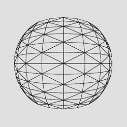
For rendering purposes, the circle is approximated with a polygon by having u assume a finite set of values in the given range. In the picture below, the circle is approximated by a 16-vertex polygon. Silver orbs represent the vertices and rods depict edges connecting those vertices. The polygon fully resides on the XY-plane.
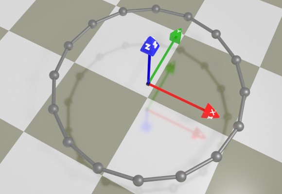
[Pic. 3: Parametrically defined circle]
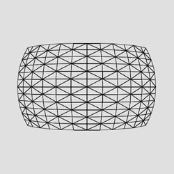
A 3D surface can be thought of as a 2D curve moving through the three-dimensional space and possibly changing its shape along the way. This is where a 2nd parameter, v, and a third equation, z(u, v), come into play. For example, a cylinder is simply a circle that moves upwards along the z-axis. The x and y equations are the same as with a circle, and the z equation is a simple linear function of v. Therefore, the equations of a cylinder with a radius of 1 and height of 1 are:
x(u, v) = sin(u)
y(u, v) = cos(u)
z(u, v) = v
u ∈ [0; 2π]
v ∈ [0; 1]
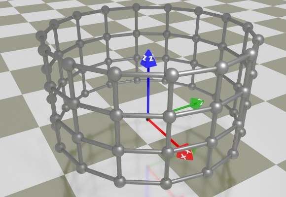
[Pic. 4: Parametrically defined cylinder]
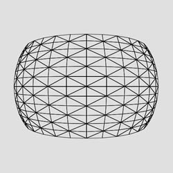
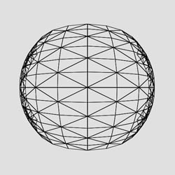
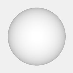
In case of a hemisphere, the circle travels upwards and collapses at the same time. Assuming that the v parameter changes from 0 to π/2, the vertical speed (alongside the z-axis) is sinusoidal, while the horizontal rate of collapse (i.e. alongside x and y axes) is cosinusoidal, so the parametric equations of a hemisphere with the radius of 1 are:
x(u, v) = cos(v) * sin(u)
y(u, v) = cos(v) * cos(u)
z(u, v) = sin(v)
u ∈ [0; 2π]
v ∈ [0; π/2]
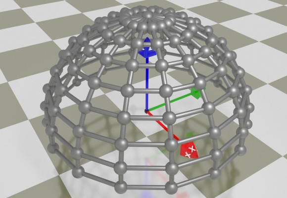
[Pic. 5: Parametrically defined sphere]
Changing the lower limit of v from 0 to -π/2 would produce a full sphere.
The code sample in the previous section defines a segment of the sphere by limiting the ranges for u and v to [-π/4; π/4] and [0.4; 0.8], respectively. Also the shape of the sphere is elongated along the z axis by using the factor 1.25 in the z-expression. These adjustments were obtained via trial and error.
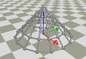
In case of a cone, the circle collapses in a linear fashion as it travels upwards. The equations of a cone with a radius of 1 and height of 1 are:
x(u, v) = (1 - v) * sin(u)
y(u, v) = (1 - v) * cos(u)
z(u, v) = v
u ∈ [0; 2π]
v ∈ [0; 1]
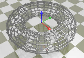
In case of a torus, the circle goes up, down and up again while its radius expands and collapses according to its own circular pattern. Therefore, the equations of a torus with the radius of R and girth of r are:
x(u, v) = (R + r * sin(v)) * sin(u)
y(u, v) = (R + r * sin(v)) * cos(u)
z(u, v) = r * cos(v)
u ∈ [0; 2π]
v ∈ [0; 2π]
Straight surfaces can be defined by parametric equations as well. The surface shown below is defined by the following equations:
x(u, v) = u
y(u, v) = v
z(u, v) = (abs(u) + abs(v)) / 2
u ∈ [-1; 1]
v ∈ [-1; 1]
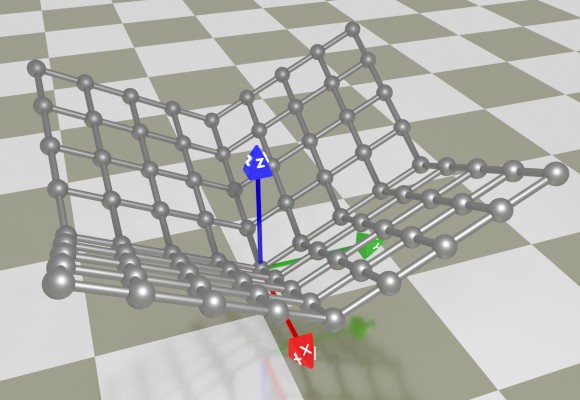
[Pic. 7: Parametrically defined non-smooth surface]
11.3 Specifying Parametric Equations via UV Object
To specify the 3D surface equations for the DrawImageUV method to use, the three formulas should be specified via the UV object's XFunc, YFunc and ZFunc properties. These properties expect string values containing the equations in a form common to most programming languages. The expressions are not case-sensitive, and may contain numbers, arithmetic operation symbols for addition (+), subtraction (-), multiplication (*), division (/) and modulo (%), nested parentheses, parameter names, special names and mathematical functions.
The parameter names are:
- u - the current iteration value of the U-parameter;
- v - the current iteration value of the V-parameter;
The following special names are currently supported:
- pi - π (3.1415926);
- rnd - a random number between 0 and 1.
The following mathematical functions are currently supported in an expression:
- abs(x) - absolute value of x;
- atn(x) - arc tangent of x, expressed in radians;
- cos(x) - cosine of x measured in radians;
- exp(x) - base-e exponential of x;
- h(x) - Heaviside step function: returns 0 if x < 0 and 1 if x ≥ 0 (useful for piecewise functions);
- log(x) - base-e logarithm of x;
- log10(x) - base-10 logarithm of x;
- sgn(x) - returns -1 if x < 0, 1 if x > 0 and 0 if x = 0;
- sin(x) - sine of x measured in radians;
- sqr(x) - square of x;
- sqrt(x) - square root of x;
- tan(x) - tangent of x measured in radians;
The domains for the U and V parameters are specified via the UMin/UMax and VMin/VMax properties, respectively. The number of iteration steps for U and V are specified via the UNum and VNum properties, respectively. The following conditions must be met:
UMax > UMin
VMax > VMin
UNum > 0
VNum > 0
When the DrawImageUV method is called, the three functions specified by XFunc, YFunc and ZFunc are evaluated for every (U, V) combination within the specified domains [UMin, UMax] and [VMin, VMax] and according to the specified number of iteration steps UNum and VNum. These evaluations produce a grid of quadrilaterals approximating the 3D surface. For a better approximation, each of the quadrilaterals is further split into two triangles in a crossed-diagonal pattern (see pictures below.) The specified image is then stretched onto the surface according to the following rules:
- The lower-left corner of the image is mapped to the point on the surface corresponding to the U/V values of (UMin, VMin).
- The upper-right corner of the image is mapped to the point on the surface corresponding to the U/V values of (UMax, VMax).
- The horizontal scanning of the image from left to right corresponds to the change of the U parameter from UMin to UMax.
- The vertical scanning of the image from bottom to top corresponds to the change of the V parameter from VMin to VMax
For example, consider a surface defined by the following set of equations:
objUV.YFunc = "u";
objUV.ZFunc = "v";
objUV.UMin = -1;
objUV.UMax = 1;
objUV.VMin = -1;
objUV.VMax = 1;
objUV.UStep = 10;
objUV.VStep = 10;
The picture of an apple is stretched onto this surface as follows (the vertex corresponding to the UMin/VMin pair is colored green):
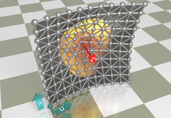
[Pic. 8: Image superimposed over triangulated surface]
The actual output from the DrawImageUV method with the property .DisplayWireframe (explained below) set to True and False, respectively, is as follows:

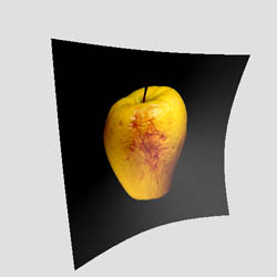
[Pic. 9: Actual DrawImageUV output]
The complete underlying code for the images above is as follows:
JpegImage obBkImage = objJpeg.CreateImage(500, 500, 0xE0E0E0);
JpegImage objImage = objJpeg.OpenImage(@"c:\path\apple.jpg");
JpegUV objUV = obBkImage.Canvas.UV;
objUV.XFunc = "sqrt( sqr(u) + sqr(v)) / 2";
objUV.YFunc = "u";
objUV.ZFunc = "v";
objUV.UMin = -1;
objUV.UMax = 1;
objUV.VMin = -1;
objUV.VMax = 1;
objUV.UStep = 10;
objUV.VStep = 10;
objUV.AmbientLight = 0.2;
objUV.DiffuseLight = 0.8;
objUV.SpecularLight = 0.5;
objUV.SpecularAlpha = 400;
objUV.DisplayWireframe = true; // or false
objUV.WireframeColor = 0xFFFFFFFF;
objUV.HideBackFace = true;
objUV.Shading = true;
objUV.SetLightVector(-1, 1, -1);
objUV.CameraX = 2.7;
objUV.CameraAngle = 34;
objUV.RotateCameraAroundAxes(0, -15, -25);
obBkImage.Canvas.DrawImageUV(objImage);
obBkImage.PNGOutput = true;
obBkImage.SaveUnique(@"c:\path\out.png");
Scaling (including negative scaling) can be applied to the image being stretched via the properties ScaleX and ScaleY. These scale values must not be equal to 0. A number whose absolute value is greater than 1 shrinks the image along the corresponding axis into a tiling pattern, and a number whose absolute value is between 0 and 1 stretches it. A negative number for ScaleX and/or ScaleY also flips the image horizontally and/or vertically, respectively. Pic. 10 (left) is obtained by adding the following lines to the code above:
objUV.ScaleX = 0.7;
objUV.ScaleY = 2.3;
...
while Pic. 10 (right) uses the values
objUV.ScaleX = 2.1;
objUV.ScaleY = - 1.4;
...
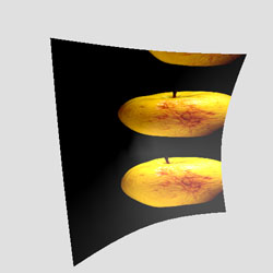
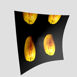
[Pic. 10: The effect of ScaleX and ScaleY properties]
11.4 Surface Visualization
11.4.1 DrawImageUV's Virtual Camera Overview
When the method
is called, the 3D surface defined via the objJpeg.Canvas.UV object's properties is evaluated, and the image represented by objImage is stretched onto it.
The 3D surface "lives" in a virtual 3D world and is viewed through the lens of a virtual camera (see Pic. 11 below.) The camera's area of vision has the shape of a square-based pyramid. The portion of the 3D surface within the camera's view (i.e. inside the "pyramid") is projected onto the camera's virtual "sensor" (shown in cyan color in the picture below.)
The 3D view from the virtual sensor is then rendered onto the canvas of the image represented by the objJpeg object (that is, the object on which the DrawImageUV method is called.)
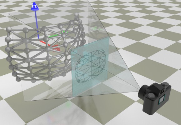
[Pic. 11: Virtual Camera and Virtual Sensor]
During rendering onto the canvas, the square-shaped 3D view is scaled in such a way that it occupies the maximum area of the canvas. If the canvas is in landscape orientation, the 3D view fully covers it vertically (Pic. 11a, left) and if it is in portrait orientation, it fully covers it horizontally (Pic. 11a, right.)
[Pic. 11a: The scaling of 3D view during rendering onto landscape (left) and portrait (right) canvases]
By default, the 3D view is centered within the canvas, but for fine-tuning purposes can be shifted up, down and sideways via the properties ShiftX and ShiftY.
11.4.2 Perspective Projection
The projection method used by the virtual camera is called "perspective projection" which approximates actual visual perception by drawing objects in the distance smaller than objects close by. The camera's view angle (i.e. the angle between two opposite sides of the "pyramid") controls the degree of perspective (i.e. the degree of size distortion between far and near objects.) The camera's default view angle is 30° and can be adjusted via the CameraAngle property. The following three images demonstrate the effect of various view angles as well as the proximity of the surface being rendered to the camera:
|
CameraX = 4.6 CameraAngle = 15 |
 |
|
CameraX = 2.3 CameraAngle = 30 |
 |
|
CameraX = 1.35 CameraAngle = 55 |
 |
In the 2nd and 3rd images above, the curvature of the peripheral portions of the surface expose the backface areas. To avoid this, the property HideBackFace should be set to True:
|
CameraX = 1.35 CameraAngle = 55 HideBackFace = true |
 |
11.4.3 Camera's Position & Orientation
By default, the camera is positioned on the X-axis at the coordinate (5, 0, 0) with its lens pointing towards the coordinate origin, in the opposite direction to the X-axis. Its vertical axis is parallel to the Z-axis of the coordinate system, and its lateral axis parallel to the Y-axis.
The camera's location in the virtual space can be changed via the properties CameraX, CameraY and CameraZ. However, changing these properties does not change the camera's orientation is space. To rotate the camera around its own center, the RotateCamera method should be used. This method accepts three angles (in degrees): the pitch angle, the bank angle and the yaw angle, to rotate the camera around its lateral (left-to-right), longitudinal (front-to-back) and vertical axes, respectively:
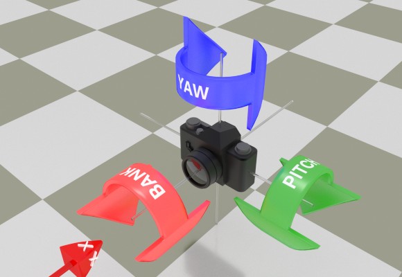
[Pic. 12: Camera's Three Rotations: Pitch, Bank & Yaw]
The order in which these three rotations are performed is significant. The RotateCamera method first performs the pitch rotation, then bank and then yaw, in that order. Therefore, the code
has the same effect as
objUV.RotateCamera( 0, 20, 0 );
but not the same effect as
objUV.RotateCamera( 10, 0, 0 );
because in the latter case, the 20° bank is performed prior to the 10° pitch.
The camera can also be rotated around the global X, Y and Z axes via the method RotateCameraAroundAxes. This method expects three angles (in degrees): the angle of rotation around the X-axis, Y-axis and Z-axis, respectively. The method performs the rotations first around the X-axis, then around the Y-axis and finally around the Z-axis. Like the RotateCamera method, the order in which these three rotations are performed is significant. Therefore the code
has the same effect as
objUV.RotateCameraAroundAxes( 0, 0, 30 );
but not the same affect as
objUV.RotateCameraAroundAxes( 0, 20, 0 );
To reset the camera to its original position, orientation and view angle, use the method ResetCamera.
11.4.4 Displaying the Wireframe
As mentioned before, the DrawImageUV method approximates a 3D surface with a finite set of vertices lying on this surface. Neighboring vertices are connected to each other with edges to form a grid of cells, and each cell is further split into two rectangles (triangulated) with a diagonal edge. This set of vertices and edges forms what is known as a "wireframe model" on which the specified image is stretched.
Normally the wireframe itself is invisible. However, during the coding and debugging phase of developing an application using the DrawImageUV method, being able to see the wireframe can be invaluable as it helps position, orient and configure the virtual camera and other parameters so that the 3D surface being rendered blends with the content of the canvas the best way possible.
To make the wireframe visible, the property DisplayWireframe must be set to True. The wireframe color (white by default) is controlled via the WireframeColor property. The wireframe thickness (1 by default) is specified via the WireframeThickness property.
By default, if DisplayWireframe is set to True, the wireframe is displayed over the image being rendered. To display the wireframe by itself, the property DisplayImage should be set to False.
11.5 Shading
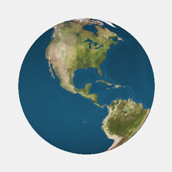
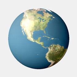
Shading in computer graphics is the process of altering the color of a surface based on its position and orientation relative to light sources to achieve a photorealistic effect. An evenly lit curved image may still appear flat (Pic. 13, top), while shading accentuates its depth (Pic. 13, bottom.)

[Pic. 13: An evenly lit image (left) and the same image with shading applied to it (right)]
The underlying script for Pic. 13 (right) is as follows:
JpegImage objImage = objJpeg.OpenImage(@"c:\path\ps_logo.png");
JpegUV objUV = obBkImage.Canvas.UV;
objUV.Shading = true;
objUV.DiffuseLight = 0.5;
objUV.AmbientLight = 0.2;
objUV.SpecularAlpha = 400;
objUV.SpecularLight = 0.1;
objUV.SetLightVector(-1, 0, 0);
objUV.XFunc = ".13 * sin(v)";
objUV.YFunc = ".13 * cos(v)";
objUV.ZFunc = "u";
objUV.VMin = -7.48;
objUV.VMax = -2.4;
objUV.UMin = -0.8;
objUV.UMax = 0.8;
objUV.UStep = 16;
objUV.VStep = 24;
objUV.ShiftX = 8;
objUV.ShiftY = 8;
objUV.CameraX = 5.8;
objUV.CameraAngle = 13;
objUV.RotateCamera(0, -45, 0);
objUV.HideBackFace = true;
obBkImage.Canvas.DrawImageUV(objImage);
obBkImage.PNGOutput = true;
obBkImage.SaveUnique(@"c:\path\out.png");
The DrawImageUV method implements Gouraud shading along with the Phong reflection model based on a single light source. To turn on shading, the UV property Shading must be set to True. The shading effect is subject to the direction of the light vector, ambient, diffuse and specular light components, and several other parameters (described below.)
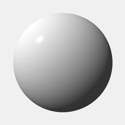
To make it easier for the application developer to select the right shading parameters, the shading of the 3D surface being rendered can be displayed by itself, without the overlaying image. To enable this debug mode, the property DisplayShading must be set to True and DisplayImage to False. The default shading parameters (AmbientLight = 0.4, DiffuseLight = 0.6, SpecularLight = 0.3, SpecularAlpha = 100 and the light vector parallel to the X-axis) produce the following shading on a spherical surface:
objUV.YFunc = "sin(v) * cos(u)";
objUV.ZFunc = "cos(v)";
objUV.UMin = 0;
objUV.UMax = 2 * Math.PI;
objUV.VMin = 0;
objUV.VMax = Math.PI;
objUV.UStep = 120;
objUV.VStep = 60;
objUV.DisplayImage = false;
objUV.DisplayShading = true;
objUV.Shading = true;
objUV.CameraX = 2.4;
[Pic. 14: Default shading applied to a sphere]
Shading is computed based on the angle between the light vector and the normal vector of each tile. The latter depends on the underlying X/Y/Z formulas and may point in the "wrong" direction. For example, the sphere shown on Pic. 14 has its normals pointing outwards. However, if the spherical surface were based on the formulas with the sin(u) and cos(u) flipped, the normals would be pointing inwards and the shading would look flat (see Pic. 15). To fix this, the property FlipNormals should be set to True.

objUV.YFunc = "sin(v) * sin(u)";
objUV.ZFunc = "cos(v)";
objUV.UMin = 0;
objUV.UMax = 2 * Math.PI;
objUV.VMin = 0;
objUV.VMax = Math.PI;
objUV.UStep = 120;
objUV.VStep = 60;
objUV.DisplayImage = false;
objUV.DisplayShading = true;
objUV.Shading = true;
objUV.CameraX = 2.4;
// We need objUV.FlipNormals = true;
[Pic. 15: Normals pointing in the wrong direction: .FlipNormals = True is required.]
Shading is based on three light components: ambient, diffuse and specular. The values for these components are specified via the properties AmbientLight, DiffuseLight and SpecularLight, respectively. The values are arbitrary but should normally be between 0 and 1, with the sum of AmbientLight and DiffuseLight not exceeding 1. When SpecularLight is greater than 0, the size of the specular highlight on the surface is determined by the SpecularAlpha property which is 100 by default but can be set to a much higher value such as 500. The higher the alpha the smaller is the highlight area.
The light vector by default points in the same direction as the camera (parallel to the X-axis in the opposite direction to it). The direction of light can be changed via the SetLightVector method.

objUV.YFunc = "sin(v) * cos(u)";
objUV.ZFunc = "cos(v)";
objUV.UMin = 0;
objUV.UMax = 2 * Math.PI;
objUV.VMin = 0;
objUV.VMax = Math.PI;
objUV.UStep = 220;
objUV.VStep = 160;
objUV.AmbientLight = 0.6;
objUV.DiffuseLight = 0.4;
objUV.SpecularLight = 0.6;
objUV.SpecularAlpha = 500;
objUV.SetLightVector( -1, 1, -1 );
...
objUV.YFunc = "sin(v) * cos(u)";
objUV.ZFunc = "cos(v)";
objUV.UMin = 0;
objUV.UMax = 2 * Math.PI;
objUV.VMin = 0;
objUV.VMax = Math.PI;
objUV.UStep = 220;
objUV.VStep = 160;
objUV.AmbientLight = 0.2;
objUV.DiffuseLight = 0.8;
objUV.SpecularLight = 0.2;
objUV.SpecularAlpha = 300;
objUV.SetLightVector(-1, 1, -1);
...
[Pic. 16: More shading examples]
When applied to an actual image, shading acts as a brightness map, or more precisely, as a brightness change map. A shading value for each pixel is a number between 0 and 1, and is displayed as a grayscale color on Pic. 14 and Pic. 16. By default, the shading value of 0 decreases the brightness of the corresponding pixel by 100 points, i.e. its R, G and B values in the range [0; 255] are decreased by 100 points each. Similarly, the shading value of 1 increases the brightness of the corresponding pixel by 100 points. The default [-100; +100] range can be changed via the properties BrightnessMin and BrightnessMax. The change in brightness is calculated as follows:
Pic. 17 below demonstrates the effect of changing these properties when an image is rendered over a sphere with the the same shading settings as in Pic. 16 (bottom).
objUV.YFunc = "sin(v) * cos(u)";
objUV.ZFunc = "-cos(v)";
objUV.UMin = 0 + Math.PI;
objUV.UMax = 2 * Math.PI + Math.PI;
objUV.VMin = 0;
objUV.VMax = Math.PI;
objUV.UStep = 80;
objUV.VStep = 40;
objUV.FlipNormals = true;
objUV.ScaleX = -1;
objUV.RotateCameraAroundAxes(0, -20, 0);
// No shading
objUV.Shading = false;
objUV.Shading = true;
objUV.AmbientLight = 0.2;
objUV.DiffuseLight = 0.8;
objUV.SpecularLight = 0.2;
objUV.SpecularAlpha = 300;
objUV.SetLightVector(-1, 1, -1);
// Default brightness properties
// objUV.BrightnessMin = -100;
// objUV.BrightnessMax = 100;
objUV.BrightnessMin = -200;
objUV.BrightnessMax = 80;
...
[Pic. 17: The effect of BrightnessMin and BrightnessMax properties]
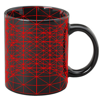
11.6 Putting It All Together
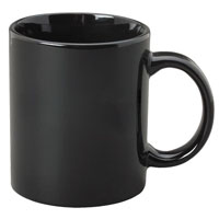
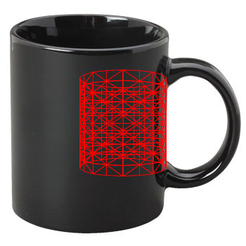
We begin by defining a 3D surface "hugging" the picture of the coffee mug tightly. Since the mug has the shape of a cylinder, we use the equations of a cylinder (see Section 11.2 - Parametric Representation of 3D Surfaces). We enable the wireframe mode and switch off the image of the painting temporarily. The first iteration produces the following result:
objUV.YFunc = "sin(u)";
objUV.ZFunc = "v";
objUV.UMin = 0;
objUV.UMax = 2 * Math.PI;
objUV.VMin = -1;
objUV.VMax = 1;
objUV.UStep = 20;
objUV.VStep = 10;
objUV.DisplayWireframe = true;
objUV.WireframeColor = 0xFFFF0000;
objUV.DisplayImage = false;
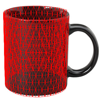
The next adjustment involves moving the camera closer to the object, and also shifting the entire picture to the left by using the ShiftX property:
objUV.CameraX = 3;
objUV.ShiftX = -48;
It is now clear that the degree of perspective used by the virtual camera is much greater than that of the camera used to photograph the mug. We reduce the degree of perspective by decreasing the virtual camera's view angle (30° by default) to about 9°. This adjustment enlarges the wireframe object, so the virtual camera needs to be moved farther away to keep the object's size unchanged. We also need to rotate the virtual camera around the Y-axis to approximately match the position of the real camera relative to the mug. For a slightly better alignment, the camera is banked 0.5°.
objUV.CameraAngle = 9;
objUV.CameraX = 9.5;
objUV.RotateCameraAroundAxes(0, -19, 0);
objUV.RotateCamera(0, -0.5, 0);
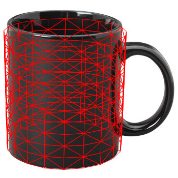
For a tighter fit, the cylinder radius is reduced from 1 to 0.96, and the the range for the V parameter is changed from [-1; 1] to [-1.05; 1.15]. The range for the U parameter is modified to have the cylinder not cover the handle area of the mug. For a better approximation, the UMax parameter is increased from 20 to 60.
objUV.XFunc = "0.96 * cos(u)";
objUV.YFunc = "0.96 * sin(u)";
objUV.VMin = -1.05;
objUV.VMax = 1.15;
objUV.UMin = -3 * Math.PI / 2 + 0.4;
objUV.UMax = Math.PI / 2 - 0.4
objUV.UStep = 60;
At this point, the wireframe model looks satisfactory. It is time to switch off the wireframe mode and bring up the image of the painting. We also need to hide the backface areas.
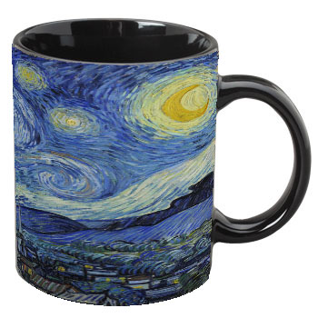
objUV.DisplayWireframe = false;
objUV.DisplayImage = true;
objUV.HideBackFace = true;
To give the image of the painting some depth, we need to turn on shading. To view the brightness map, the image should temporarily be switched off and shading-display mode enabled. Also, the light should come slightly from the left to match the shading of the mug, and therefore a call to SetLightVector is in order.
objUV.Shading = true;
objUV.DisplayImage = false;
objUV.DisplayShading = true;
objUV.AmbientLight = 0.05;
objUV.DiffuseLight = 0.95;
objUV.SetLightVector(-3, 1, 0);
And for the final result, we adjust BrightnessMin and BrightnessMax, switch off the shading-display mode and turn the image of the painting back on:
objUV.DisplayImage = true;
objUV.DisplayShading = false;
objUV.BrightnessMax = 60;
objUV.BrightnessMin = -200;
The entire script is presented below:
<%@ Import Namespace="Persits.Jpeg"%>
<html>
<head>
<title>AspJpeg.NET User Manual Chapter 11 -- Painting on Mug</title>
<script runat="server" languge="C#">
void Page_Load( Object Source, EventArgs E)
{
// Create instance of JpegManager
JpegManager objJpeg = new JpegManager();
// Open image of a baseball cap as background
JpegImage objBkImage =
objJpeg.OpenImage(Server.MapPath("../images/mug.jpg"));
// Open logo image to map to 3D surface
JpegImage objImage =
objJpeg.OpenImage(Server.MapPath("../images/vangogh.jpg"));
// Specify UV parameters
JpegUV objUV = objBkImage.Canvas.UV;
// Parametric equations of a spheroid
objUV.XFunc = "cos(u)";
objUV.XFunc = "0.96 * cos(u)";
objUV.YFunc = "0.96 * sin(u)";
objUV.ZFunc = "v";
objUV.UMin = -3 * Math.PI / 2 + 0.4f;
objUV.UMax = Math.PI / 2 - 0.4f;
objUV.VMin = -1.05f;
objUV.VMax = 1.15f;
objUV.UStep = 60;
objUV.VStep = 10;
// Fine-tuning the position over canvas
objUV.ShiftX = -48;
// Camera view angle
objUV.CameraAngle = 9f;
// Do now show backface areas
objUV.HideBackFace = true;
// Camera location and rotation
objUV.CameraX = 9.5f;
objUV.RotateCameraAroundAxes( 0, -20, 0 );
objUV.RotateCamera( 0, -0.5f, 0 );
// Shading
objUV.AmbientLight = 0.05f;
objUV.DiffuseLight = 0.95f;
objUV.SetLightVector( -3, 1, 0 );
objUV.Shading = true;
objUV.BrightnessMin = -200;
objUV.BrightnessMax = 60;
// Draw image on the canvas
objBkImage.Canvas.DrawImageUV( objImage );
string strFilename =
objBkImage.SaveUnique(Server.MapPath("mugpainting.jpg"));
OutputImage.ImageUrl = strFilename;
}
</script>
</head>
<form runat="server">
<asp:image runat="server" id="OutputImage"/>
</form>
</html>
<%@ Import Namespace="Persits.Jpeg"%>
<html>
<head>
<title>AspJpeg.NET User Manual Chapter 11 -- Painting on Mug</title>
<script runat="server" languge="vb">
Sub Page_Load( Source As Object, E As EventArgs)
' Create instance of JpegManager
Dim objJpeg As JpegManager = New JpegManager()
' Open image of a baseball cap as background
Dim objBkImage As JpegImage =
objJpeg.OpenImage(Server.MapPath("../images/mug.jpg"))
' Open logo image to map to 3D surface
Dim objImage As JpegImage =
objJpeg.OpenImage(Server.MapPath("../images/vangogh.jpg"))
' Specify UV parameters
Dim objUV As JpegUV = objBkImage.Canvas.UV
' Parametric equations of a cylinder
objUV.XFunc = "cos(u)"
objUV.XFunc = "0.96 * cos(u)"
objUV.YFunc = "0.96 * sin(u)"
objUV.ZFunc = "v"
objUV.UMin = -3 * Math.PI / 2 + 0.4f
objUV.UMax = Math.PI / 2 - 0.4f
objUV.VMin = -1.05f
objUV.VMax = 1.15f
objUV.UStep = 60
objUV.VStep = 10
' Fine-tuning the position over canvas
objUV.ShiftX = -48
' Camera view angle
objUV.CameraAngle = 9f
' Do now show backface areas
objUV.HideBackFace = true
' Camera location and rotation
objUV.CameraX = 9.5f
objUV.RotateCameraAroundAxes( 0, -20, 0 )
objUV.RotateCamera( 0, -0.5f, 0 )
' Shading
objUV.AmbientLight = 0.05f
objUV.DiffuseLight = 0.95f
objUV.SetLightVector( -3, 1, 0 )
objUV.Shading = true
objUV.BrightnessMin = -200
objUV.BrightnessMax = 60
' Draw image on the canvas
objBkImage.Canvas.DrawImageUV(objImage)
Dim strFilename As String =
objBkImage.SaveUnique(Server.MapPath("mugpainting.jpg"))
OutputImage.ImageUrl = strFilename
End Sub
</script>
</head>
<form runat="server">
<asp:image runat="server" id="OutputImage"/>
</form>
</html>
Click the links below to run this code sample:
The script above is also used in Live Demo #8 - UV Projection.
11.7 Handling Rectangular Shapes
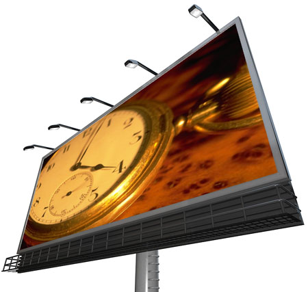
An older version of AspJpeg (2.5) introduced a feature enabling an image to be stretched over an arbitrary 4-point polygon to emulate a perspective projection effect. This feature is described in Section 6.4 of this user manual and summarized in Pic. 18 below. An image undergoing this type of deformation may be subject to significant distortions as seen on Pic. 18 (right.)

[Pic. 18: Quasi-perspective projection of Section 6.4: round shapes are clearly distorted.]
Being a true perspective projector, the DrawImageUV method produces a much more accurate and distortion-free output. But to have the projection align well with the 4-point shape on the background (such as the picture of the billboard on Pic. 18), the position, rotation and view angle of the virtual camera need to be somehow calculated based on the coordinates of the 4 points of the shape and overall background dimensions. The manual trial-and-error approach used in the previous section may not yield satisfactory results within a reasonable timeframe.
To help deal with rectangular shapes, we have developed UVFinder, a JavaScript-based application, which takes the width and height of the background image and the coordinates of the 4 points of the desired projection as input, and produces the camera parameters in the form of a VB or C# script as output. The image below (Pic. 19) was generated with the help of UVFinder.
[Pic. 19: True perspective projection with DrawImageUV method: no distortions.]
Click here to launch UVFinder in a separate window.
Once started, UVFinder runs indefinitely until stopped by the user. In search for a good alignment between the desired 4-point outline and the actual projection, the application sifts through millions of camera positions in a matter of minutes, and displays the one with the lowest deviation (calculated as the sum of distances between the corresponding points) it has found so far. It also displays the current best projection graphically over the specified outline (Pic. 20).
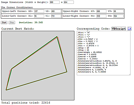
[Pic. 20: UVFinder Interface.]
For a perfect alignment, the process should run until the deviation is down to single digits, or better yet, falls below 1. The following VBScript output was generated by UVFinder for the image size and coordinate values applicable to the billboard image above. It took several hours of processing to bring the deviation down to a mere 0.104.
objUV.YFunc = "u";
objUV.ZFunc = "v";
objUV.UMin =-2.45592 / 2;
objUV.UMax = 2.45592 / 2;
objUV.VMin = -0.81449;
objUV.VMax = -0.81449 + 1;
objUV.UStep = 10;
objUV.VStep = 10;
objUV.CameraAngle = 29.97892;
objUV.CameraX = 2.18979;
objUV.CameraY = 0.00089;
objUV.CameraZ = -0.09539;
objUV.RotateCameraAroundAxes(10.32625, 0, 0);
objUV.RotateCameraAroundAxes(0, 32.60264, 0);
objUV.RotateCameraAroundAxes(0, 0, 55.94800);
objUV.RotateCamera(1.13119, 0, 0);
objUV.RotateCamera(0, 3.65646, 0);
objUV.RotateCamera(0, 0, 10.36281);
The code above is used in Live Demo #7 - Perspective Projection.
11.8 Summary of UV Properties and Methods
The following table summarizes all the properties and methods of the UV object. Required properties are shown in bold. Default values are shown in parentheses.
YFunc
ZFunc
UMin
UMax
VMin
VMax
UNum
VNum
CameraY (0)
CameraZ (0)
RotateCamera()
RotateCameraAroundAxes()
DiffuseLight (0.6)
SpecularLight (0.3)
SpecularAlpha (100)
SetLightVector() (-1, 0, 0)
BrightnessMax (100)
